The Linux PWM Userspace Interface
Overview
The value of the resistor that you use to protect an LED determines its brightness. To change the brightness of the LED, you use a potentiometer instead of a plain resistor. If you want to control LED brightness from software though, you do Pulse Width Modulation (PWM) on an IO pin to which the LED is attached.
Here in this topic we will be doing just that,
Attach a PCA9685 PWM controller to a Raspberry Pi.
Connect an LED to the controller
Control the LED brightness by adjusting PWM parameters
Learn how to use the Linux userspace PWM interface. We do not write one single line of code.
Pulse Width Modulation (PWM)
Electronic engineers can come up with much better explanations of PWM than I ever could. Please watch the following video if are not yet familiar with PWM (you may skip the second half which is about building a PWM circuit).
Why An External PWM Controller?
One can use a computer - an Arduino, or any other microcontroller, or a PC - to drive the PWM signal by a program that runs on the CPU. But the more PWM lines you have to drive, the more complex the program will become:
You need more elaborate timer management. Multiplex multiple PWM channels onto the same physical timer, for example, that is adjusted frequently as PWM parameters change.
Other parts of the program may want to have their own share of the CPU. Correctness of those parts might suffer as they interfere with PWM timers.
Microcontrollers usually run some kind of realtime OS, or no OS at all. Whether there are timer delays depends on the quality of the OS’s timer management, naturally, and all of the caveats above apply.
Linux is much more complex than any bare-metal OS that is usually used for such applications. It has a network stack that operates in the background, and a filesystem and block IO layer, and maybe a graphics stack, other software such as remote login programs, a webserver, and much more. There is much more contention for CPU resources. Linux’s contention management strategies are quite elaborate, and the programmer is not always in control of every single piece of it.
Driving a PWM signal at a millisecond frequency means that the PWM software would have to compete with a possibly unknown number of other processes in the system - leading to glitches and hard-to-detect errors. While Linux, as deployed on the Raspberry, has real-time capabilities that try to give wakeup guarantees, this is a best-effort approach. Turning Linux into a realtime OS that gives hard guarantees is no fun is rather hard. There is a version of a realtime preemption kernel for the Pi, I recommend to go out of its way if this is possible.
Attaching a PCA9685 PWM controller is really simple as the remainder of this topic will show, and to use it from Linux is even simpler.
Wiring, Setup, and Testing
That said, here’s the wiring.
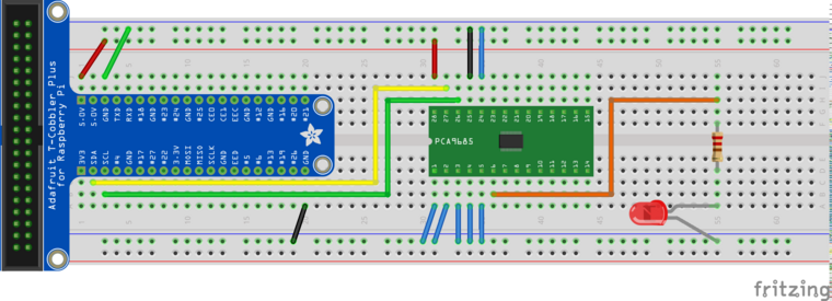
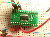
Adapter for SSOP packages
The PCA9685 is connected over I2C, which is a two-wire bus where each
device has a 7-bit address. Note we connect the address lines
A0-A5 to ground. According to the data sheet, the highest address
bit is 1, which gives an address value of 0b1000000, or
0x40.
If everything is ok, we should be able to detect the chip at this
address. Enable I2C on the Raspberry, by editing /boot/config.txt,
so that it contains the following line (that line is already there,
it’s only commented out),
/boot/config.txt¶dtparam=i2c_arm=on
Reboot. Now we see a filesystem representation of the I2C bus in
/dev. This is bus number 1 (as opposed to bus number 0 which is
used internally for the camera interface, and which is not exported to
userspace).
$ ls -l /dev/i2c*
crw-rw---- 1 root i2c 89, 1 Aug 10 09:13 /dev/i2c-1
We are now in a position to probe that bus for devices, using the
i2c-detect program.
$ i2cdetect -y 1
     0  1  2  3  4  5  6  7  8  9  a  b  c  d  e  f
00:          -- -- -- -- -- -- -- -- -- -- -- -- --
10: -- -- -- -- -- -- -- -- -- -- -- -- -- -- -- --
20: -- -- -- -- -- -- -- -- -- -- -- -- -- -- -- --
30: -- -- -- -- -- -- -- -- -- -- -- -- -- -- -- --
40: 40 -- -- -- -- -- -- -- -- -- -- -- -- -- -- --
50: -- -- -- -- -- -- -- -- -- -- -- -- -- -- -- --
60: -- -- -- -- -- -- -- -- -- -- -- -- -- -- -- --
70: 70 -- -- -- -- -- -- --
The addresses are in hexadecimal notation. We see address 0x40
which is what we expect from the wiring. The PCA has a second address,
0x70. That is something like the broadcast address to use when
there are multiple PCA’s on the same bus, and which you want to give
commands simultaneously. We don’t use this feature so we can ignore
that second address.
Ok, so the device is there. We do not want to talk to it “by hand”,
using /dev/i2c-1. We could, see here for
how, but we won’t. The Linux kernel has dedicated PWM subsystem that
is used to control PWM devices, regardless of their peculiarities such
as whether they are connected on a I2C bus, or SPI, or whatnot. There
is a driver for the PCA9685; enable that in /boot/config.txt.
To learn how this is done, you browse through
/boot/overlays/README which is a definitive list of devicetree
overlays available. Find the PCA9685’s overlay which is responsible
for hardware initialization, and finally announces to the kernel that
there is a device that requires driver loading. For reference, here’s
the corresponding snippet.
/boot/overlays/README¶Name: i2c-pwm-pca9685a
Info: Adds support for an NXP PCA9685A I2C PWM controller on i2c_arm
Load: dtoverlay=i2c-pwm-pca9685a,<param>=<val>
Params: addr I2C address of PCA9685A (default 0x40)
Put that in /boot/config.txt,
/boot/config.txt¶dtoverlay=i2c-pwm-pca9685a,addr=0x40
Reboot.
Concluding the setup, we quickly check the list of modules loaded, and see how the ones are in place that are relevant for our purposes.
$ lsmod
Module                  Size  Used by
... lots omitted, leaving ours in place ...
pwm_pca9685            16384  0
regmap_i2c             16384  1 pwm_pca9685
i2c_bcm2835            16384  0
i2c_dev                16384  0
Strictly speaking, there is no need for i2c_dev. It makes
/dev/i2c-1 available to userspace; we intend to use the PWM driver
pwm_pca9685 and the PWM userspace interface that it
provides. That driver does I2C communication with our PCA9685
internally in kernel space.
Finally, setup done; read on for how we do PWM on the commandline.
Talk to Chip Using the sysfs Interface
Now that we have everything in place, lets quickly see how to use the
sysfs PWM interface 1. The pwm_pca9685 driver
exports the device in a directory under the sysfs tree,
$ ls -l /sys/class/pwm/
total 0
lrwxrwxrwx 1 root gpio 0 Aug 10 09:41 pwmchip0 -> ../../devices/platform/soc/3f804000.i2c/i2c-1/1-0040/pwm/pwmchip0
/sys/class/pwm/pwmchip0 is actually a symbolic link to a device
which obviously is located in an area in the sysfs tree that is
responsible for I2C. We do not care. Change the current working
directory into there.
Note
Unfortunately, the default permissions of the sysfs PWM interface
are root/root, so we have to be logged in as root. sudo -i
will do the job, for example.
$ sudo -i

SSH is enabled and the default password for the 'pi' user has not been changed.
This is a security risk - please login as the 'pi' user and type 'passwd' to set a new password.

#
(The # prompt shows us that we are logged in as root now. We
ignore security warnings.)
Now, shift our butt into the chip, and see what’s there,
# cd /sys/class/pwm/pwmchip0
# ls -l
total 0
lrwxrwxrwx 1 root root    0 Aug 10 10:14 device -> ../../../1-0040
--w------- 1 root root 4096 Aug 10 10:14 export
-r--r--r-- 1 root root 4096 Aug 10 10:14 npwm
drwxr-xr-x 2 root root    0 Aug 10 10:14 power
lrwxrwxrwx 1 root root    0 Aug 10 10:14 subsystem -> ../../../../../../../../class/pwm
-rw-r--r-- 1 root root 4096 Aug 10 09:41 uevent
--w------- 1 root root 4096 Aug 10 10:14 unexport
PCA9685 metadata all over. Note that don’t see any mention of PWM
channels. We connected the LED to the PCA’s pin 6, which is PWM
channel 0. Export that to userspace, by writing 0 into the
export file 2.
# echo 0 > export
# ls -l
total 0
...
drwxr-xr-x 3 root root    0 Aug 10 10:21 pwm0
...
Aha, that created a chip subdirectory, pwm0. Shift butt into, and
see what’s there.
# ls -l
total 0
...
-rw-r--r-- 1 root root 4096 Aug 10 10:23 duty_cycle
-rw-r--r-- 1 root root 4096 Aug 10 10:23 period
...
Sounds much like PWM. The files period and duty_cycle, like
the export file above, are not persistent on any storage
media. Rather, they actually provided by the kernel who sits under the
surface and observes any read/write operations.
Lets configure PWM, by writing time periods (in nanoseconds) into those files. First the PWM period,
# echo 1000000 > period
This does nothing because the duty cycle is still 0,
# cat duty_cycle
0
Bring LED to full brightness,
# echo 1000000 > duty_cycle
Dim it,
# echo 500000 > duty_cycle
# echo 400000 > duty_cycle
# echo 300000 > duty_cycle
...
Fade it programmatically 3,
# for d in 1000000 800000 600000 400000 200000 100000 50000 0; do
>    echo $d > duty_cycle
>    sleep 0.5
> done
#
All that in a video, for ultimate visual experience. Manual focus on the camera is not easy to have though, I apologize.
Conclusion
Linux has a nice way of integrating hardware interfaces like I2C, PWM, GPIO, and much more. The interfaces that the kenel devlopers created go together very well with the good old UNIX paradigm: everything is a file.
The PWM interface is just one of those interfaces; as you explore what else can be done with Linux, you will encounter many interfaces that are designed in this way. For me as a trainer, it is always a great pleasure to show how easy it is to write a working prototype in no time, requiring as little code and hardware experience as possible.
Footnotes
- 1
As always, there is more. Read it up in the kernel documentation
- 2
Channels are not exported by default. This is to avoid conflicts with kernel driver which might have grabbed the channel for their own purposes.
- 3
The brightness is not quite linear with the duty cycle, this is why the value might look a bit odd.